How much a conveyor system moves in an hour is not decided by the rated speed of the conveyors. It depends on the task mix, the shared equipment, the control rules and the bottleneck nodes. Pallet lines usually choke at right-angle transfers (lift-and-transfer units), lifts, RGVs and the warehouse infeed and outfeed points; carton lines usually choke at merges, transfers, lifts, scanning and weighing stations, and manual workstations. Our method has three steps: calculate the cycle time of every node, check its load against peak-hour demand, then run a simulation to see queues and buffers.
The short answer
- On a line where one flow passes through nodes in series, capacity is set by the slowest node; where several flows share a lift, transfer unit or RGV, you also have to account for the task mix and the release rules.
- On pallet conveyors with zone-by-zone release, capacity is set by the zone index time; dividing conveyor speed by pallet length overstates it.
- For every node, the specification should state demand, design capacity, calculation conditions and acceptance method, with the load limit and design margin written down as project-agreed values.
Two formulas for conveyor capacity calculation
Continuous conveying has one basic formula: flow (items/h) = speed (m/min) × 60 ÷ pitch (m). Pitch is the length of the load in the direction of travel plus the gap to the next one. A branch line at 15 m/min with a 1.5 m pitch carries 600 cartons/h; a main line at 60 m/min with a 1.0 m pitch carries 3,600 cartons/h. When you check the worst case, take the pitch of the longest load; when you forecast real capacity, weight it by the carton mix. The gap also has to leave enough time for barcode reading, photocells and the downstream divert to act.
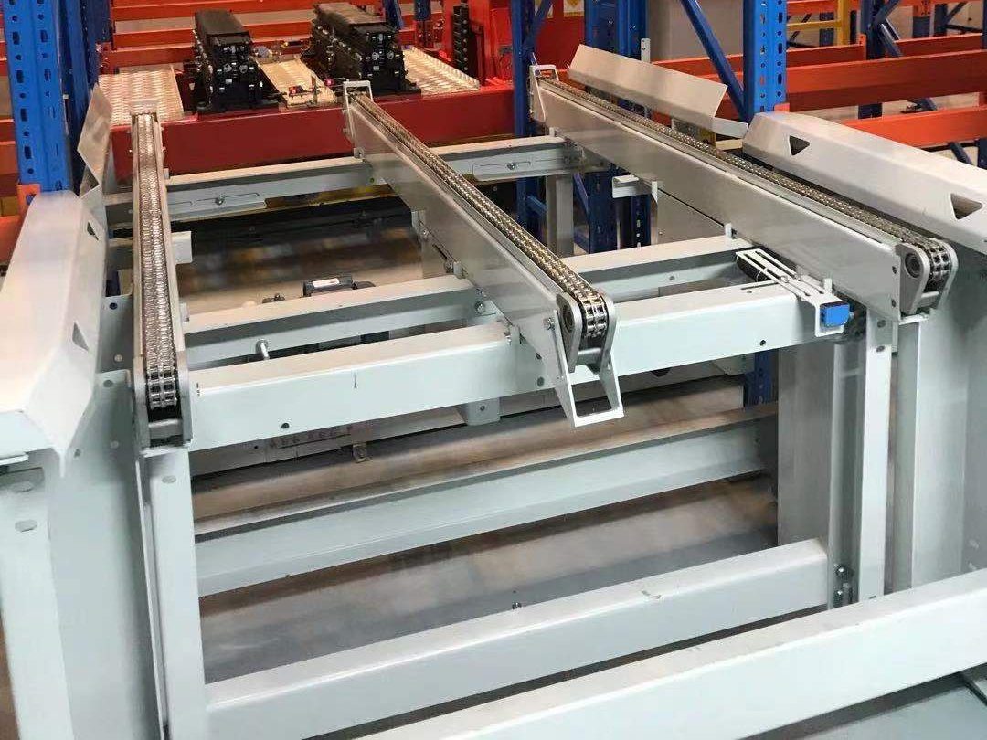
Pallet conveyors are normally zoned for accumulation, one pallet per zone. With zone-by-zone release, node capacity follows from the zone index time. If the pallet accelerates and brakes at the same rate and reaches line speed within the zone, T = travel distance ÷ speed + speed ÷ acceleration + response time; a zone too short to reach line speed needs the triangular-profile calculation instead. A 2.7 m chain conveyor at 0.3 m/s (18 m/min), with 0.5 m/s² acceleration and 0.5 s response, needs about 10.1 s per zone, a theoretical capacity of about 356 pallets/h. At 12 m/min over a 3 m zone it is about 15.9 s, or about 226 pallets/h. Continuous release can go faster; check it against the actual control method. These figures alone show that straight sections have more theoretical capacity than any node where the pallet has to stop to change direction, lift or be checked.
How many pallets per hour can a pallet conveyor move?
On some pallet projects, the bottleneck is the right-angle transfer. The pallet has to stop, lift, and leave in the other direction. At 12 m/min, with a 1,200 mm pallet and a 2.4 s lift time, it travels 1.5 m on the rollers and 1.8 m on the chains; add the lift, plus acceleration and braking at 0.5 m/s² and a 0.5 s response for each of the two moves, and one transfer takes about 20.7 s. That is a theoretical capacity of about 174 pallets/h, or about 148 pallets/h at 85% scheduling efficiency. In our team's past projects, design rates for pallet right-angle transfers ranged roughly from 110 to 154 pallets/h, depending on project conditions. Turntables commonly need 6–10 s to rotate, but compare full cycles (drive in, rotate, drive out); rotation time alone is misleading. The transfer units themselves are on our pallet conveyor systems page.
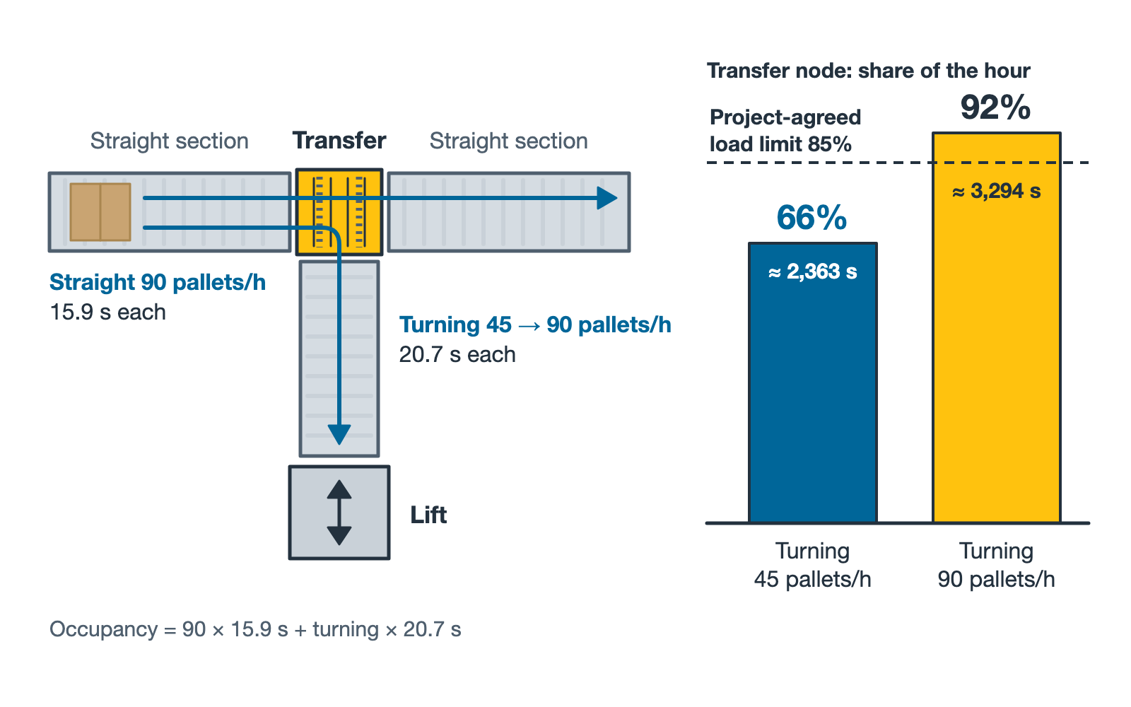
Transfer nodes often handle both straight-through and turning pallets, so weight them by the task mix. Say 90 pallets/h go straight (15.9 s each) and 45 pallets/h turn (20.7 s each): together they occupy about 2,363 s, or 66% of the hour. Double the turning flow to 90 pallets/h and occupancy climbs to about 3,294 s, or 92%, so this node passes an 85% load limit before the straight sections on either side do.
A typical worked example: a pallet AS/RS must handle 90 pallets/h in and 90 pallets/h out, plus 30 empty pallets/h, with 1,200 × 1,000 pallets of up to 500 kg each. The conveyor system uses chain conveyors, roller conveyors, transfer units and reciprocating pallet lifts. Per unit, the cycle calculation gives about 131 pallets/h for a chain conveyor, about 129 for a roller conveyor, about 120 for a transfer unit and about 101 for a lift. These are single-unit capacities; the total flow still has to be split by route across the units and checked again. The order of magnitude is already clear, though: the straight sections have the most slack, and the lifts and transfer units are the tightest.
Lifts and RGVs are frequent bottlenecks as well. For a reciprocating pallet lift, in our team's past projects, a single unit with one pallet position, loads up to 1.5 t, about 40 m/min vertical speed and about 12 m/min infeed and outfeed conveying managed roughly 60–90 pallets/h at a lift height of around 6 m, often dropping to about 40 pallets/h above 15 m. Height is not the only factor: vertical acceleration, safety gate opening and closing, and handover time all change the result, and the calculation sheet should list each item. A single-station RGV at 160 m/min, with an average travel of about 26 m and an on-board chain conveyor at 12 m/min for pick-up and drop-off, manages about 50–60 pallets/h; longer travel or more docking points push it lower. See rail-guided vehicles (RGV). A twin-station RGV carries two pallets per trip, but it only gets close to double the capacity when inbound and outbound tasks can actually be paired.
In multi-level warehouses, a common choke point is where the conveyor changes direction and then feeds a lift. The turn and the lift sit in series: a pallet's transit times add, but the junction's throughput is set by the slower of the two plus any blocking or interlocking between them. Check this junction separately, simulate the pair, and leave one or two pallet positions of buffer before and after the lift.
Infeed, outfeed and auxiliary stations belong in the calculation too. Where contour, over-height, weight and barcode checks at the infeed are configured as stop-and-check, the pallet has to stand still, which adds one more stop node; rejected pallets need a return lane either way. An inline stretch wrapper handles about 20–25 pallets/h per unit and a pallet changer about 30 cycles/h; when outbound flow approaches these numbers, consider parallel units or a bypass.
Where carton conveyors get stuck
On carton lines, we look first at whether the merges will queue. Angled-wheel merges usually run at 30°, with main-line speeds commonly between 45 and 90 m/min. The more branch lines feed in, the fewer gaps remain on the main line and the longer the branch queues become. So check merge nodes against main-line occupancy, and write the release priority of each branch into the WCS.
Transfer and divert units have catalogue limits. Carton pop-up transfers (roller or belt) are typically rated up to 1,500 cartons/h (≤ 50 kg per item) and swing-arm diverters up to 2,400 items/h. If the main-line flow is higher, you need a faster divert method or more divert points; see merge and divert modules.
Level-to-level lifting is a trade between capacity and redundancy. Reciprocating carton lifts (≤ 100 kg per item) run at about 100–400 cartons/h; they get close to the upper figure at 4–6 m of lift and often fall to about 100 cartons/h at 15–20 m. With a single cycle of about 20 s, one unit does about 180 cartons/h. Continuous lifts (C-type or Z-type) reach 1,200 cartons/h, and a single spiral conveyor up to 2,000 cartons/h. Once inter-level flow reaches several hundred cartons/h, the choice is between a continuous lift and several reciprocating ones. With several reciprocating lifts, the others keep running when one stops; a continuous lift has more capacity, but when it stops, a whole level is cut off. Maintenance windows, floor space, and the floor openings with their fire closures belong in the same comparison. See vertical lifts.
For scanning, weighing and dimensioning stations, first establish whether they are stop-and-go or continuous. Stop-and-go weighing needs the item to come to rest, so its cycle is drive in, settle, drive out. Continuous dynamic weighing and DWS work without stopping the conveyor, but items must already be singulated and keep a minimum gap; a single DWS unit commonly handles 3,000–6,000 items/h. The higher the no-read rate, the busier the reject and recirculation routes. If weights are used for invoicing or settlement, the scale may fall under legal metrology. Both the EU and Türkiye separate automatic weighing instruments from non-automatic ones, according to whether an operator has to intervene during weighing, and regulate them under two different sets of rules (listed in the references). Go by the current consolidated EU texts and the current Turkish amendments. Whether conformity assessment applies depends on the intended use and on national law under Directives 2014/31/EU and 2014/32/EU; the accuracy class only sets the performance requirements. Confirm it with the metrology authority in the project's country.
Manual workstations and truck loading have no catalogue figure. Barcode re-labelling, labelling, checking and picking capacity depend on the actual work content and have to be checked against measured task times. Some specifications for manual carton loading with telescopic belt conveyors ask for about 1,500 cartons/h; the number of people, carton weight and stacking pattern all have to be confirmed for each project.
The table below lists calculated values, catalogue values or our project experience for common nodes under the stated conditions. They are not guaranteed figures.
| Node | Typical capacity | Conditions |
|---|---|---|
| Pallet chain / roller straight section | about 226–356 pallets/h (theoretical) | 12–18 m/min, 2.7–3 m zone, zone-by-zone release |
| Pallet right-angle transfer (calculated) | about 148 pallets/h | 12 m/min, 1,200 mm pallet, 2.4 s lift, 0.5 m/s², 0.5 s response per move, 85% scheduling efficiency |
| Pallet right-angle transfer (project design values) | about 110–154 pallets/h | different projects, different speed and scheduling assumptions |
| Reciprocating pallet lift | about 60–90 pallets/h at 6 m; about 40 pallets/h above 15 m | team project experience; single unit, one pallet position, ≤ 1.5 t, about 40 m/min vertical; gate and handover times checked per project |
| Single-station RGV | about 50–60 pallets/h | team project experience; 160 m/min, average travel about 26 m, on-board conveying at 12 m/min |
| Inline stretch wrapper | about 20–25 pallets/h | team project experience; single unit, check against number of wraps and film type |
| Carton branch / main line | 600 / 3,600 cartons/h | 15 m/min at 1.5 m pitch / 60 m/min at 1.0 m pitch |
| Carton pop-up transfer | ≤ 1,500 cartons/h | catalogue limit; ≤ 50 kg per item, roller or belt type |
| Reciprocating carton lift | about 100–400 cartons/h | catalogue value; ≤ 100 kg per item, near upper figure at 4–6 m, about 100 cartons/h at 15–20 m |
| Continuous lift / spiral | ≤ 1,200 / ≤ 2,000 cartons/h | catalogue limits; spiral lift 1–12 m, ≤ 50 kg per item |
| DWS | 3,000–6,000 items/h | catalogue value; continuous, ≤ 2.5 m/s, ≤ 30 kg per item, singulated |
| Telescopic belt loading | about 1,500 cartons/h | project requirement; staffing and carton type confirmed per project |
Design stage: calculate, simulate, then write it into the specification
We start with a static calculation. Draw the conveyor system as a node diagram and number the nodes. For each node, list every task type that passes it in the peak hour (inbound, outbound, empty pallets, returns, recirculation) with its count, and weight by cycle time to get the occupancy. A convention we often use on projects is design capacity of at least 1.2 times peak demand, with no single node above 85% load at peak. That is experience, not a clause from any standard, and the specification should also state how long the peak window is and whether equipment availability is deducted separately.
Once the static numbers stack up, discrete-event simulation shows where queues will build at peak. Its inputs are the peak task profile in 15-minute slices, the cycle time of each node, the WCS release rules and breakdown downtime; the outputs are node utilisation, queue length and buffer occupancy. Run at least three scenarios: inbound and outbound peaking together, one lift or RGV out of service, and the outbound wave right after a shift change.
The results of both steps go into the specification, so acceptance does not turn into an argument. Attach a node capacity table listing, for each node, its type and location, maximum load size and weight, straight-through versus turning ratio, peak demand, design capacity, calculation conditions, load limit and acceptance method. At FAT, measure the cycle times of transfers, lifts and RGVs; at SAT, run mixed tasks continuously and count with WCS records to measure whole-line throughput.
Retrofits and phased expansion: what comes first?
When an existing line falls short, do not rush to replace equipment. Capture a day of peak data first. If the PLC or WCS logs photocell triggers and task times, export at least one peak day and count, per node and per 15 minutes, the number of passes, blocked time (downstream full) and starved time (upstream empty). If there are no logs, add temporary counters or film it. The bottleneck is easy to spot: the queue upstream never clears and the line downstream keeps running dry. Then measure the cycle time of the suspect nodes and check the records for false photocell triggers and barcode read retries. Quite a few "capacity problems" turn out to be release logic or merge priority. Our usual order of fixes: logic first, then buffers, then a bypass or parallel unit, and new equipment last.
You can usually see on site whether the buffer is big enough. A common case: after a miniload goes live, the picker waits about three minutes between one tote going back into storage and the next one arriving, and the operator just stands there until an outbound recirculation buffer is added. Miniload buffers should be designed from the goods-to-person cycle up front, not patched in after go-live.
Sometimes the shortfall has nothing to do with the nodes. A common case: a sorter line fed from a public low-voltage grid has its circuit breakers tripping now and then. Measure and diagnose first: overload, earth leakage, selectivity and voltage quality. Then the fix has two halves. Put the control system (PLC, WCS servers) on UPS so that a voltage dip does not cut control power or lose data; a UPS only protects what is connected to it. Deal with nuisance trips in the power circuits by correcting breakers and earthing to the sorter manufacturer's requirement (TN-S in this case) and the local wiring rules (TS HD 60364 in Türkiye), checked by a qualified electrical engineer. Put this kind of operating risk on the maintenance list at tender stage.
In Türkiye, Europe and the Middle East, many projects are phased expansions inside existing buildings, and phase one has to leave room for phase two. Size the main line and key nodes for the final volume, or reserve space for a parallel line. Put interface sections at future branch points so phase two does not require taking apart phase-one conveyors. Reserve the position and floor opening for a second lift, and an extension section for the RGV rail. Leave enough PLC I/O, WCS equipment capacity, power capacity and control cabinet space for phase two. Connecting phase two needs a shutdown plan, ideally with the changeover on a weekend or holiday. Openings that cross fire compartments should be confirmed together with the fire design when phase one is submitted for permits.
Frequently asked questions
Q: If we double the conveyor speed, does the line capacity double?
A: Usually not. Lifting, response and positioning are fixed times that make up a large part of the cycle time at transfers, lifts, RGVs and manual stations. They do not shrink when speed goes up, so the bottleneck nodes gain only a little.
Q: How much margin should a pallet conveyor design have?
A: There is no single standard. We often design for capacity of at least 1.2 times peak demand, with an 85% load limit per node; what matters is stating the peak window and the availability basis alongside it. If the business is growing fast or downtime is expensive, increase the margin.
Q: Our existing line cannot hit its numbers. Is it time to replace equipment?
A: Not yet. Use PLC or WCS records, or temporary counters, to find the node with a queue upstream and gaps downstream, and measure its cycle time. Many bottlenecks are solved by a PLC or WCS logic change or an added buffer; new equipment is usually the last step.
The worked examples in this article are typical cases; experience figures come from our team's past projects and are only a first guide. Each project is calculated on its own data.
References
- EU: Directive 2014/32/EU, Measuring Instruments Directive (Annex VIII covers automatic weighing instruments, MI-006): https://eur-lex.europa.eu/eli/dir/2014/32/oj/eng
- EU: Directive 2014/31/EU, Non-automatic Weighing Instruments Directive: https://eur-lex.europa.eu/eli/dir/2014/31/oj/eng
- OIML: R 51-1 Automatic catchweighing instruments (2006 edition): https://www.oiml.org/en/files/pdf_r/r051-p-e06.pdf
- Türkiye, Official Gazette of 29 June 2016, No. 29757: Ölçü Aletleri Yönetmeliği (2014/32/AB), Measuring Instruments Regulation: https://www.resmigazete.gov.tr/eskiler/2016/06/20160629-22.htm
- Türkiye, Official Gazette of 2 July 2016, No. 29760: Otomatik Olmayan Tartı Aletleri Yönetmeliği (2014/31/AB), Non-automatic Weighing Instruments Regulation: https://www.resmigazete.gov.tr/eskiler/2016/07/20160702-3.htm
If you are planning a new conveyor system, or an existing line is not reaching its numbers, you are welcome to send the layout, peak-hour figures or WCS logs to the EMMANUEL Technical Team via the contact form and talk the nodes through with us.